Data modeling
Fast track: In this field, you will read about data modeling, i.e. how to break down the user requirements to diagrams, which can then be converted to a database. We introduce terms like entities, relations to show examples on how to make entity-relationship diagrams on different levels of details. You will also read about different types of relationships.
You can save time by reading it fast, just to get a grasp of what these terms are.
Exercise: Read about data modeling, as we will follow this path to implement the database structure in DuckDB on the next field.
Entities and relations
From the business needs we can easily get to the database structure via an entity-relationship model (ER model). How?
We need a model, which reflects to the business needs. More specifically, we need an entity-relationship model. It contains the basic information about the business domain:
- entities, which are definable objects with attributes and
- relations between them.
For example, if the business domain is to track cars of owners, then the entities are: owners, cars; and the relation between them: [an owner] 'has' [a car]. An entity can have attributes like age or weight etc. A relation can be marked with numbers: how many belongs to how many (1 or many). It has a direction. Both sides of the relation can be marked with 'can be zero' or not. If it has to be more than one, then it is mandatory. If 0 is allowed, then we say it is nullable.
The most natural approach to make a model is to draw a figure. A nice diagram type for this purpose is the Entity-relationship diagram (ERD). We'll look at examples, implement our own diagrams, and finally we'll end up in a database structure.
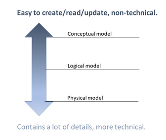
There are 3 stages of an ERD, and it depends on the situation (like for example talking with the customer, dev team huddle, showing the database structure), which one is the best fit.
| Note |
|---|
| Different sources describe these models slightly differently. So it's not set in stone. |
1. Conceptual:
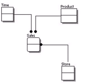
- List of square shapes (representation of entities) and lines (representation of relations).
- Easy to understand, or to draw on a white board, or to update; but holds only basic information.
2. Logical:
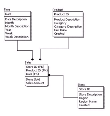
- List of attributes to every entity, including an identifier (ID).
- An attribute is either key or non-key attribute. If the attribute is unique, it is a key attribute (ID); every other attribute is a non-key attribute. Key attributes are above the line, non-key attributes are below the line.
- Primary keys are defined to identify entities. It ensures uniqueness, and non-null values. There can be only 1 primary key in a table.
- Foreign keys are defined to make relations between columns of tables. If car.person_id is valid only if it is included in the person table as an id, then create a foreign key reference in the car table to the person.
- Possible number of connections is included on both ends of the relation arrows. (Not like on the attached figure. :) )
- A connection arrow between person and car showing (2)---(1) on the ends means that "1 person has 1 car", and "1 car belongs to 2 people".
- A connection arrow between person and car showing (2)---(*) on the ends means that "1 person has any number of cars", and "1 car belongs to 2 people".
- Put a 0 next to the number, if 0 is also allowed.
- Tool can be used to create it.
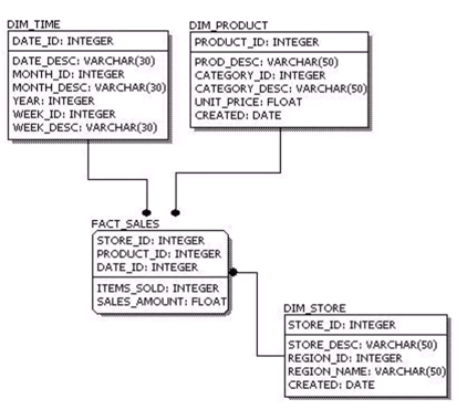
3. Physical: Database specific implementation of the model.
- Tables, columns, data types, default values are defined.
- Precise, but hard to understand for users.
Relationship types
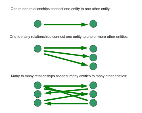
See the references below for more explanation and examples.
Typical relations: "has", "can have", "working on", "uses", "creates", "belongs to" etc.
References: